In the current validation example, we investigate wind pressure coefficient (Cp) for both main structural members (Cp,ave) and secondary structural members such as cladding or façade systems (Cp,local) based on NBC 2020 [1] and Japanese Wind Tunnel Data Base for low-rise building with 45 degree slope. The recommended setting for three-dimensional flat roof with sharp eaves will be described in the next part.
In the current validation example, we investigate wind pressure value for both general structural design (Cp,10) and local structural design such as cladding or façade systems (Cp,1) based on EN 1991-1-4 flat roof example [1] and Japanese Wind Tunnel Data Base . The recommended setting for three-dimensional flat roof with sharp eaves will be described in the next part.

In the current validation example, we investigate wind pressure coefficient (Cp) of flat roof and walls with ASCE7-22 [1]. In the section 28.3 (Wind loads - main wind force resisting system) and Figure 28.3-1 (load case 1), there is a table which shows Cp value for different roof angle.
The Architectural Institute of Japan (AIJ) has presented a number of well-known benchmark scenarios of wind simulation.
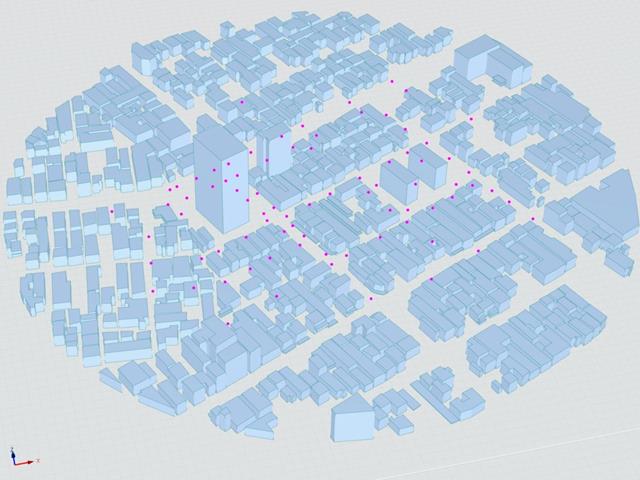
The following article deals with "Case E - Building Complex in Actual Urban Area with Dense Concentration of Low-Rise Buildings in Niigata City".
In the following, the described scenario is simulated in RWIND& 2 and the results are compared with the simulated and experimental results by AIJ.

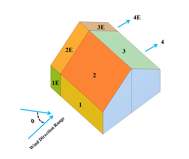
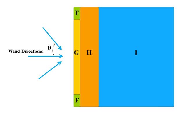
In the current validation example, we investigate wind pressure value for both general structural designs (Cp,10) and cladding or façade design (Cp,1) of rectangular plan buildings with EN 1991-1-4 [1]. There are three dimensional cases that we will explain more about if in the next part.
The Architectural Institute of Japan (AIJ) has presented a number of well-known benchmark scenarios of wind simulation.
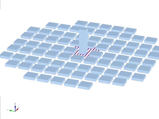
The following article deals with "Case D - High-Rise Building Among City Blocks".
In the following, the described scenario is simulated in RWIND 2 and the results are compared with the simulated and experimental results by the AIJ.
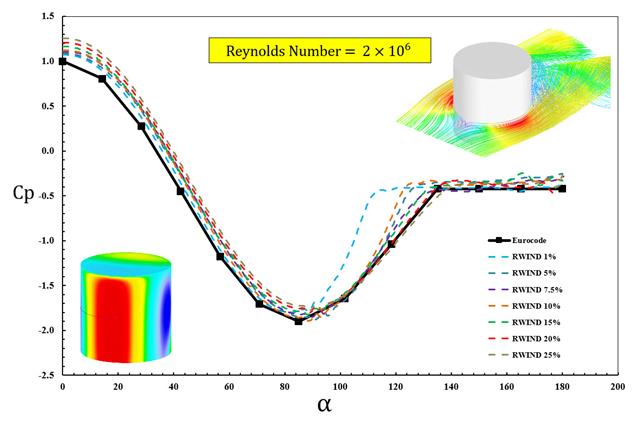
The available standards, such as EN 1991-1-4 [1], ASCE/SEI 7-16, and NBC 2015 presented wind load parameters such as wind pressure coefficient (Cp) for basic shapes. The important point is how to calculate wind load parameters faster and more accurately rather than working on time-consuming as well as sometimes complicated formulas in standards.
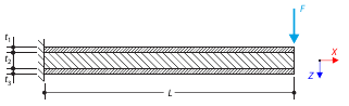
A sandwich cantilever consists of three layers (the core and two faces). It is fixed on the left end and loaded by a concentrated force on the right end.
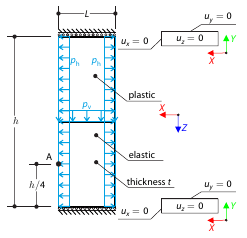
Determine the maximum deformation of a wall divided into two equal parts. The upper and lower parts are made of an elasto-plastic and an elastic material, respectively, and both end planes are restricted to move in the vertical direction. The wall's self-weight is neglected; its edges are loaded with horizontal pressure ph, and the middle plane by vertical pressure.
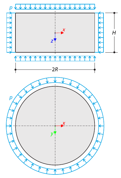
A cylinder made of elasto-plastic soil is subjected to triaxial test conditions. Neglecting the self-weight, the goal is to determine the limit vertical stress for shear stress failure. An initial hydrostatic stress of 100 kPa is considered.
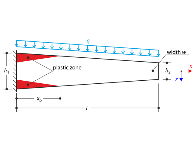
A tapered cantilever is fully fixed on the left end and subjected to a continuous load q. Small deformations are considered and the self-weight is neglected in this example. Determine the maximum deflection.
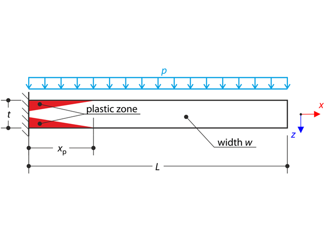
A thin plate is fully fixed on the left end and subjected to a uniform pressure. The plate is brought into the elastic-plastic state by the uniform pressure.
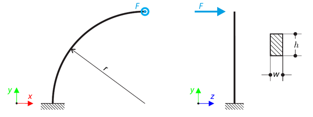
A quarter-circle beam with a rectangular cross-section is loaded by means of an out-of-plane force. This force causes a bending moment, torsional moment, and transverse force. While neglecting self-weight, determine the total deflection of the curved beam.
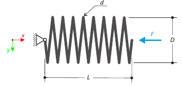
A closely coiled helical spring is loaded by a compression force. The spring has middle diameter D, wire diameter d, and it consists of i turns. The total length of the spring is L. Determine the total deflection of the spring for the member model and one‑turn deflection for the solid model.
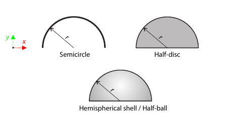
Determine the y-position of the center of gravity for the given bodies, namely semicircle, half-disc, hemispherical shell, and half-ball.
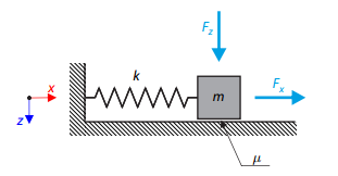
A simple oscillator consists of mass m (considered only in the x-direction) and linear spring of stiffness k. The mass is embedded on a surface with Coulomb friction and is loaded by constant-in-time axial and transverse forces.
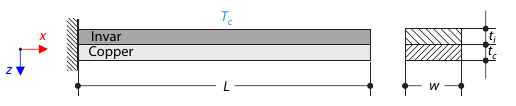
A bimetallic strip is composed of invar and copper. The left end of the bimetallic strip is fixed, and the right end is free, loaded by temperature difference. While neglecting self-weight, determine the deflection of the bimetallic strip (free end).
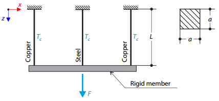
A truss structure consists of three rods (one steel and two copper) joined by a rigid member. The structure is loaded by a concentrated force and a temperature difference. While neglecting self‑weight, determine the total deflection of the structure.
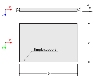
A rectangular steel plate of dimensions is simply supported at its edges. Determine the natural frequencies of the rectangular plate.
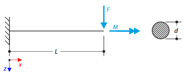
A cantilever with a circular cross‑section is loaded by a concentrated bending force and torque. The aim of this verification example is to compare the reduced stress according to the von Mises and Tresca theories.